If it were up to me, every airplane in the world would have an angle of attack indicator with L/DMAX clearly labeled and every pilot would be required to recite the following before getting a license:
- Maximum endurance of jet powered aircraft occurs at L/DMAX
- Maximum range of propeller driven aircraft occurs at L/DMAX
- Maximum climb angle for jet powered aircraft occurs at L/DMAX
- Maximum power off glide range for jet or propeller powered aircraft occurs at L/DMAX
— James Albright
Updated:
2026-07-23
L/DMAX Curve
But it isn't up to me and, at least in the United States, there are no regulatory requirements for any of this. If you have an angle of attack indicator, you are in pretty good shape. Even if you don't, you should be able to come up with a chart of your own to help you out should you ever need a maximum power off glide speed. By the way, if you don't have an AOA indicator, you really need to memorize a few critical deck angles should your pitot-static system ever go on strike. (For example, what pitch angle is required for level flight at takeoff power all engine and engine-out?)
First we'll explain the aero behind L/DMAX and then a little about how to determine your own particular L/DMAX AOA. If you don't have an AOA indicator, we'll cover how to build a chart.
Yes, engines are more reliable these days. Yes, I am paranoid. No, you don't have to do any of this. But you should.
1
AOA, lift, drag
Angle of Attack
AOA versus Lift
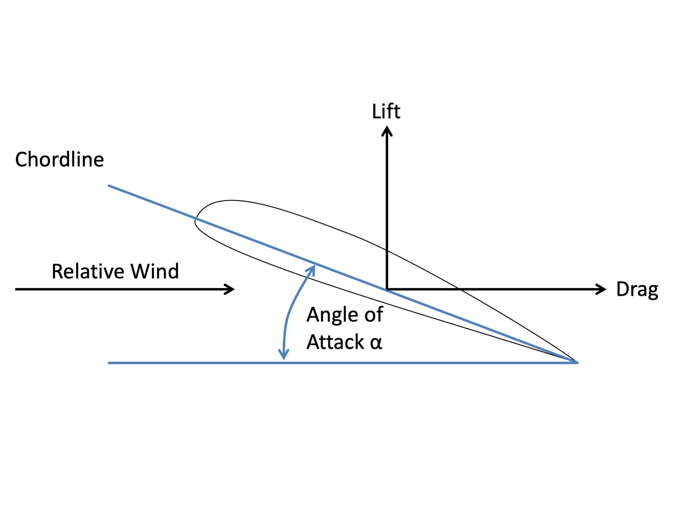
The angle of attack is the angle between the chord line of the wing and the relative wind. More about this:
Lift
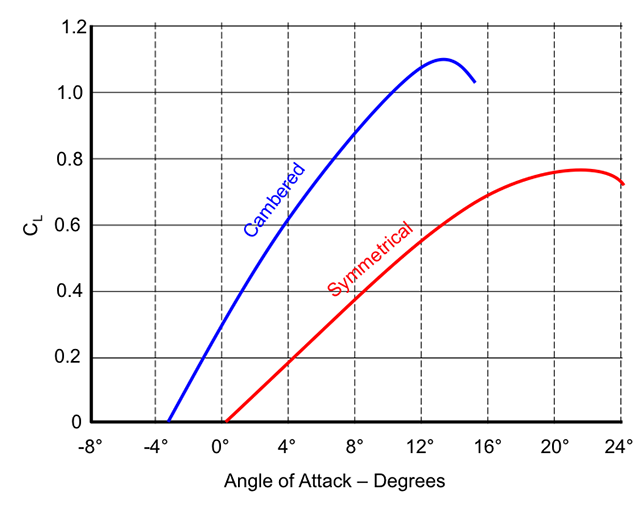
AOA versus Lift
A wing produces a force upon the aircraft known as "aerodynamic force." This force can be broken into two components: lift acts perpendicular to the relative wind, drag parallel to it. More about this:
Drag
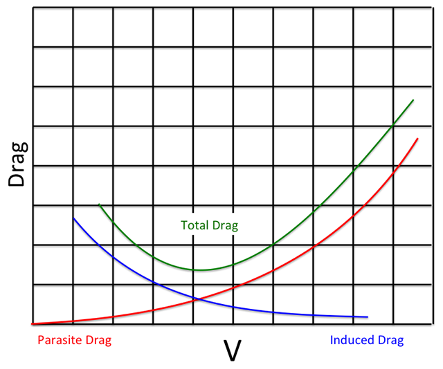
Drag versus Velocity
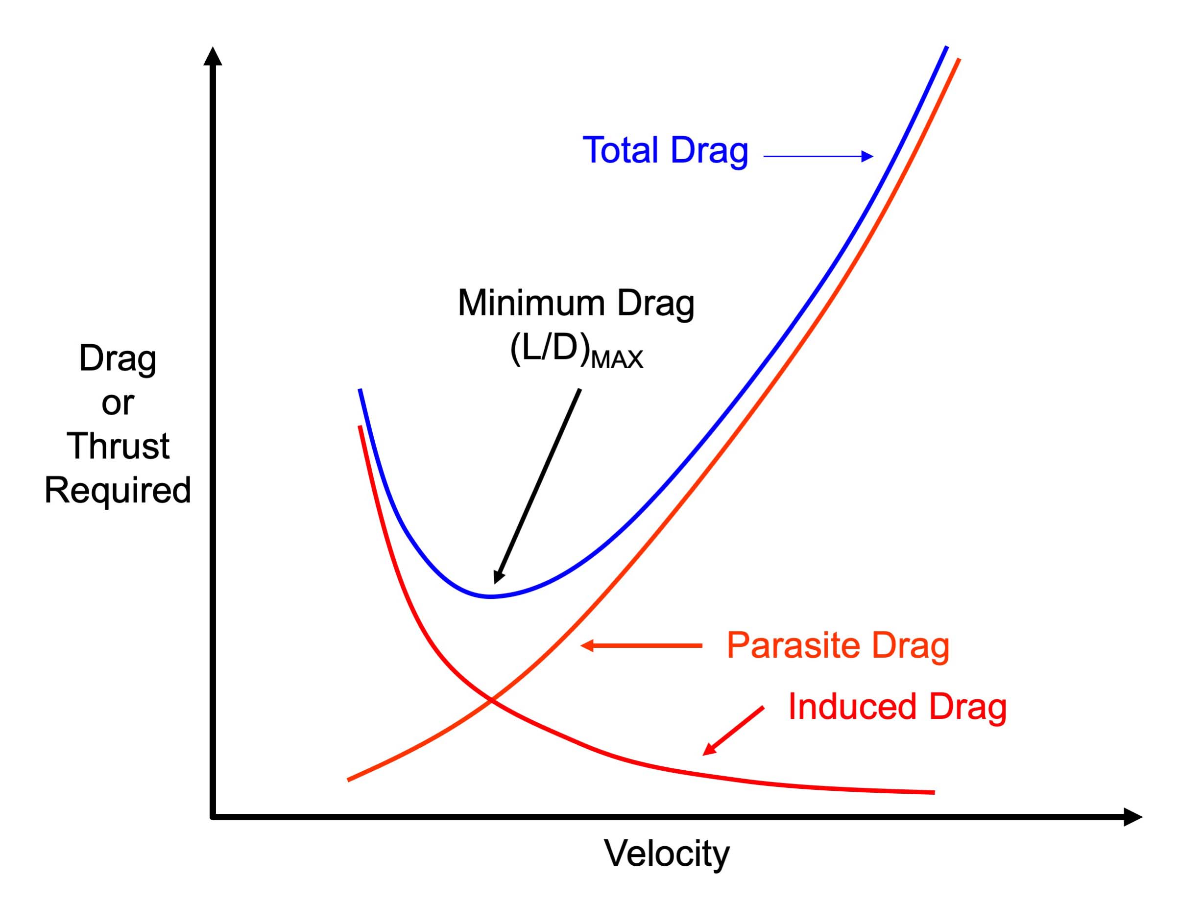
Part of the aerodynamic force generated by the wing points aft and parallel to the relative wind is known as induced drag. This type of drag starts high and decreases with airspeed. Another type of drag, known as parasite drag, is just what you think of when you think of air resistance against an object. Parasite drag starts low and becomes very high. More about this:
2
L/DMAX
- A factor more important in airplane performance considerations is the lift-drag ratio, L/D. With the lift and drag data available for the airplane, the proportions of CL and CD can be calculated for each specific angle of attack. The resulting plot of lift-drag ratio with angle of attack shows that L/D increases to some maximum then decreases at the higher lift coefficients and angles of attack. Note that the maximum lift-drag ratio (L/D)MAX occurs at one specific angle of attack and lift coefficient. If the airplane is operated in steady flight at (L/D)MAX, the total drag is a a minimum. Any angle of attack lower or higher than (L/D)MAX reduces the lift-drag ratio and consequently increases the total drag for a given airplane lift.
- Many important items of airplane performance are obtained in flight at (L/D)MAX. Typical performance conditions which occur at (L/D)MAX are:
- maximum endurance of jet powered airplanes
- maximum range of propeller driven airplanes
- maximum climb angle for jet powered airplanes
- maximum power-off glide range, jet or prop
- The most immediately interesting of these items is the power-off glide range of an airplane. By examining the forces acting on a airplane during a glide, it can be shown that the glide ratio is numerically equal to the lift-drag ratio. For example, if the airplane in a glide had an (L/D) of 15, each mile of altitude is traded for 15 miles of horizontal distance. Such a fact implies that the airplane should be flown at (L/D)MAX to obtain the greatest glide distance.
- An unbelievable feature of gliding performance is the effect of airplane gross weight. Since the maximum lift-drag ratio of a given airplane is an intrinsic property of the aerodynamic configuration, gross weight will not affect the gliding performance.
Source: ATC Manual 51-3, page 32.
3
T-38 example
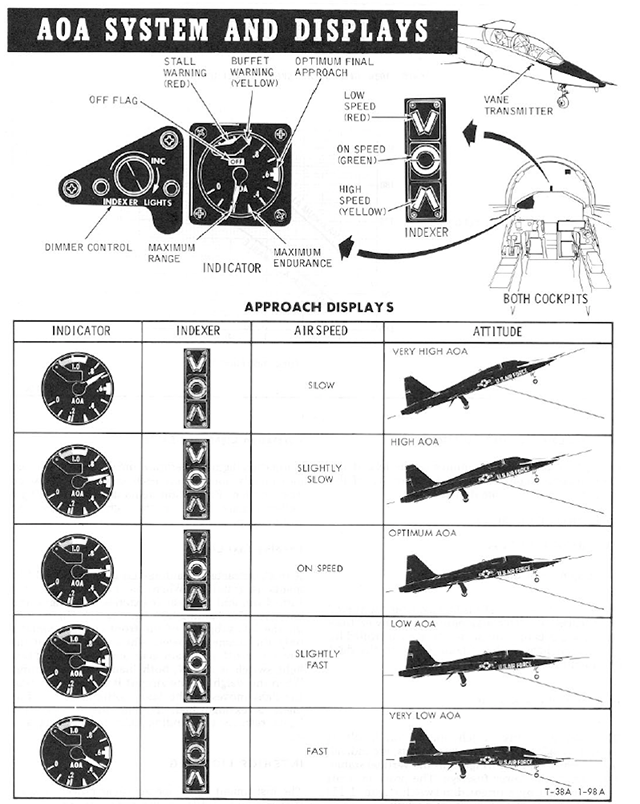
T-38 Angle of Attack Indicator
The good folks at Northrop equipped the T-38 Talon with an Angle of Attack indicator with all the good stuff right on the gauge:
- Maximum Range: 0.18 AOA
- Maximum Endurance: 0.30 AOA
- Optimal Approach: 0.60 AOA
- Buffet Warning: 0.90 AOA
- Stall: 1.00 AOA
Chances are your business jet or airliner isn't so equipped. Too bad, this is the kind of stuff that can save your life. Not to worry, most aircraft seem to have the exact same numbers as that T-38 when it comes to AOA. You can easily find at least two of them.
4
Finding your aircraft's critical AOAs
Your manuals
Your aircraft manuals may have clues for some of your important angles of attack. In the case of the G450, this is all we have:
- If it is suspected that one or more airspeed indications (including standby airspeed) is erroneous or unreliable with or without Air Data Comparator flags being displayed, stabilize pitch, power setting (fuel flow) and normalized angle of attack on the AOA indicator as appropriate to the phase of flight.
- Clean configuration: 0.50 or lower
- Flaps 10, 20, or 39: 0.59 or lower until on approach
- If an overspeed condition is displayed or the overspeed aural warning is generated, check pitch attitude, power setting and AOA. Maintain AOA between 0.30 and 0.50. If the overspeed condition persists, reduce power setting and increase AOA to maintain level flight but no higher than 0.50 AOA.
Source: G450 Aircraft Operating Manual, §05-16-20
A small dose of aero
If you feel so inclined, you can devise a "V-G" diagram for your aircraft that plots velocity against G-loads, to determine your manuevering speed. See Operating Flight Strength for a primer on how to do this. Then look at Approach Speed Additives for the math that tells you an aircraft like a G450 with two engines and a 2.0 G loading limit on approach has an AOA of 0.66 at VREF. Note: I used 0.67 AOA when rounding to the nearest number, but I've since been convinced rounding down would be more conservative.
I've watched AOA closely in every Gulfstream I've flown and 0.66 AOA at VREF looks right, but since we usually fly with a wind additive, the AOA will be more like 0.50 on approach.
Other aircraft
Newer Gulfstreams have better discussions about aerodynamics and the following quote from the GVII-G500 Aircraft Operating Manual illustrated the 0.66 number's value: "For max endurance (e.g. holding or loitering), the aircraft should be flown at 0.66 AOA (allowing good maneuver and stall margin) at an altitude that has the best combination of low temperature (good) and low Mach number (also good)."
Putting it all together
You should record your aircraft's performance over several flights and try to collect multiple data points for identical configurations. I've done that for the G450 and here's what I found:
- Takeoff Rotation: 0.2 to 0.3
- Cruise (0.80 Mach): 0.15 to 0.20
- Cruise (LRC): 0.30
- Pattern: 0.40
- VREF: 0.66
- VREF "plus": 0.50
By definition all of these except 0.80 Mach are regardless of weight.
A common misconception is that since you stall at 1.00 AOA and your approach speed is 1.30 times stall speed (for most, but not all aircraft), then your approach angle of attack should be 1.00 / 1.30 = 0.77 AOA. But that is not the case, the 1.30 is based on speed not angles. Approach angle of attack tends to be between 0.50 and 0.60.
I know, from doing the math, that the AOA for VREF is 0.66. But by the time you add at least 5 knots (because that is minimum approach speed), you end up with something less. If you want to see the math: Approach Speed Additives. (This is for a GVII, but the math is the same for the G450.)
I am often asked what AOA to fly in the event both engines flame out. We know this should be (L/D)MAX but our AOA indicators don't show this. We also know that in some Gulfstreams, we are told 0.66 is the right number but that number includes maneuver and stall margins. My opinion: fly an AOA of 0.66 if you need to maneuver or winds could make a stall margin important. If you really have to stretch the glide, an AOA between 0.66 and 0.75 (where the Pitch Limit Indicator appears) might be the way to go.
For those without an AOA indicator
Your process is the same, but you will end up with airspeeds that will change with weight. There is talk at the FAA to make angle of attack indicators mandatory equipment. Let's hope that happens.
References
(Source material)
Air Training Command Manual 51-3, Aerodynamics for Pilots, 15 November 1963
Dole, Charles E., Flight Theory and Aerodynamics, 1981, John Wiley & Sons, Inc, New York, NY, 1981.
Gulfstream G450 Airplane Flight Manual, Revision 35, April 18, 2013.
Gulfstream G450 Aircraft Operating Manual, Revision 35, April 30, 2013.
Gulfstream G450 Performance Handbook, GAC-AC-G450-OPS-0003, Revision 20, November 30, 2011
Technical Order 1T-38A-1, T-38A/B Flight Manual, USAF Series, 1 July 1978.
Please note: Gulfstream Aerospace Corporation has no affiliation or connection whatsoever with this website, and Gulfstream does not review, endorse, or approve any of the content included on the site. As a result, Gulfstream is not responsible or liable for your use of any materials or information obtained from this site.